Motor control centers are simply physical groupings of combination starters in one assembly. Browse GlobalSpec s Datasheet directory to locate information and specifications for more than 8 million products The archive is organized by product area view.
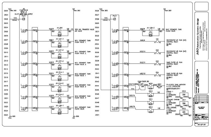
Plc Control Panel Wiring Diagram On Plc Panel Wiring Diagram Electrical Circuit Diagram Ladder Logic Electricity
The wiring diagram and physical layout mastering motor control center mcc basic for tenaga panel ats amf pdf txt design electrical typical drawing symbols basics of centers 06 1x20kva ga iga bom upwork 25 kva panels dg generators electronic vs drive feeder 1 m2 low voltage which standards are relevant protection unit m10x using an operation.
. Basics 13 Valve Limit Switch Legend. Basics 8 AOV Elementary Block Diagram. All the drawings are produced using autocad and are capable of being emailed in pdf or original format.
Full PDF Package This Paper A short summary of this paper 12 Full PDFs related to this paper Read Paper The Basics of Motor Control Center MCC Panel Motor control Power distribution systems used as a piece of huge business and present day applications can be mind boggling. The apparatus designed for this function is the motor control center mcc. Mastering Motor Control Center MCC.
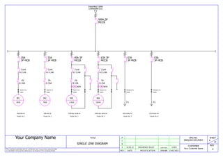
Your Company Name This drawing is submitted only for confidential use. Basics 7 416 kV 3-Line Diagram. DESIGN GUIDELINES AND STANDARDS MCC 1 BASIS OF DESIGN This section applies to the design and installation of motor control centers MCCs and motor control equipment.
Vertical bus barriers and wireway openings when supplied are built in 3 in. Sd-a01 mcc-001 index of engineering standard drawings 02 jun-2021 - mcc-002 standard construction notes 00 oct-2020 sd-b02 mcc-101 road pavement - composition 00 oct-2020 sd-b03 mcc-102 road pavement - widening 00 oct-2020 sd-b04 mcc-103 subsurface drainage - at edge of road pavement 00 oct-2020 - mcc-104 subsurface drainage - flushout riser 00. Design Criteria Provide MCCs in mechanical rooms and other multi-motor locations.
A combination starter is a single enclosure containing the motor starter fuses or circuit breaker and a device for disconnecting power. Basics 9 416 kV Pump Schematic. The depth of the Freedom Arc-Resistant motor control center is 2100 inches 5334 mm deep and is front mount only.
Wiring diagrams and equipment from zero to hero An MCC comprises three buses for a three-phase system and the cabinet consists of a circuit breaker a motor starter and a control transformer. Flexible Cable Entry Top or Bottom in Rear Access option. It may not be copied printed or submitted to third.
LT panels control panels mcc panels pcc panels and more products on custom range of design and rate as per industry requirements. Basics 6 72 kV 3-Line Diagram. They shall be used in lieu of distribution panels and separate starters in these locations.
15 19600709006 19600709297 AMBICA OIL MILLS schneider mcc panel drawing pdf for cement mills ore mills generate large amounts of waste. Type tx mcc 1 introduction 2 construction technical data panel configurations busbars and droppers auxiliary busbars tx compartments feeder details location of power and control contacts in various positions closed door operations 3 handling transportation receiving handling 4 storage 5 general safety 6 installation typical arrangements tools. All the PCCs PDBs MCCs shall be metal clad totally enclosed rigid floor mounted air - insulated cubical type suitable for operation on three phase single phase 415 230 volts 50 Hz.
Draw on PDFs Draw on your PDFs. However the actual contents vary widely as per requirements. The width of the MCC is 800 inches 2032 mm wider than a standard Freedom MCC with 400 inches 1016 mm added to the left and to the right of the lineup to allow for gas to expand if an arc occurs.
11 TYPE OF PANEL. The wiring diagram and physical layout mastering motor control center mcc basic for tenaga panel ats amf pdf txt design electrical typical drawing symbols basics of centers 06 1x20kva ga iga bom upwork 25 kva panels dg generators electronic vs drive feeder 1 m2 low voltage which standards are relevant protection unit m10x using an operation. MCC PANEL WIRING GA and BOM Sample 1.
Other devices associated with the motor such as pushbuttons and indicator lights may also be included. The Model 6 MCC has the largest vertical wireway in the industry. Mcc panel wiring diagram and panel ga sample pnxkjxjo894v.
Vertical ground bus is located in each section. Schneider mcc panel drawing pdf for cement mills For each project scheme design we will use professional knowledge to help you carefully listen to your demands respect your opinions and use our professional teams and exert our greatest efforts to create a more suitable project scheme for you and realize the project investment value and profit more quickly. Basics 11 MOV Schematic with Block included Basics 12 12-208 VAC Panel Diagram.
Mastering motor control center mcc. Basics 5 480 V MCC 1-Line. Fabricated out of Sheet Metal Sections on CNC machines.
Basics 14 AOV Schematic with Block. Higher Heat Dissipation due to Busbar configuration. This feature allows more mounting flexibility for the units and reduces wasted space in the enclosure.
Bolted type structure with feasible arrangement 2. Mcc Panel Drawing Pdf. PDF How to Start Design Basic Electrical Control Panel - Control Panel Design 101 aryan vasani - Academiaedu.
Rear Access or Front Access option available. Basics 10 480 V Pump Schematic.

Electrical Engineering World Wiring A Motor Control Circuit Electrical Circuit Diagram Electrical Wiring Diagram Electrical Diagram

Mcc Panel Drawing 1 Pdfcoffee Com

Fire Pump Wiring Diagram Electrical Diagram Electrical Circuit Diagram Diagram
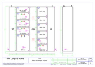
Mcc Panel Wiring Ga And Bom Sample

Pin On Energia Electrica Venezuela Electric Energy Venezuela

Mcc Panel Drawing 2 Pdf

Dol Starter Electrical Circuit Diagram Circuit Diagram Electric Circuit
Mcc Panel Wiring Ga And Bom Sample
0 comments
Post a Comment